PIONEER DJM-850
Installation
Connections
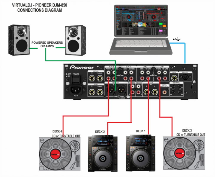
- Connect your computer to USB port at the top panel of Pioneer DJM-850
- Optionally, connect each of your deck’s RCA cables to ANALOG INPUTs 1.to 4 respectively, depending on which software deck you wish to control.
If it’s a CD player, use any of the CD/LINE Inputs
If it’s a turntable, use the PHONE Inputs of CH1 and CH4. Secure the ground wire to a Phono Ground terminal. - Set the SOURCE selector at the top panel for DECKs 1 to 4 to USB
- Connect the Pioneer DJM-850 with AC power using the provided cable and power on the unit
Note: Usage of turntables or CD players (for DVS) is not necessary. The mixer may be used as a pure MIDI mixer. VirtualDJ is also offering the ability to control all the software decks with even with a single timecode unit. See Timecode (DVS).
Drivers
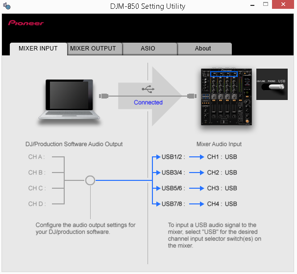
If the drivers are properly installed, the DJM-850 Setting Utility will appear each time you connect your DJM-850 with your computer via the USB port.
See Advanced Setup for further details.
.
VirtualDJ 8 Setup
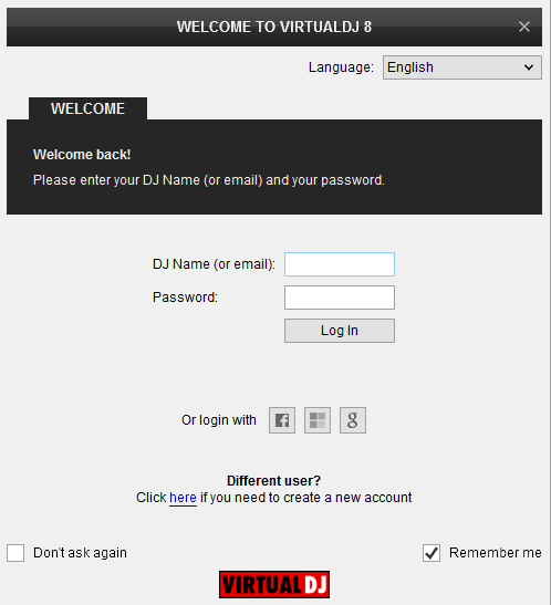
Once VirtualDJ 8 is launched, a Login Window will appear. Login with your virtualdj.com account credentials.
A Pro Infinity or a Pro Subscription License is required to use the Pioneer DJM-850. Without any of the above Licenses, the mixer will operate for 10 minutes each time you restart VirtualDJ.
http://www.virtualdj.com/buy/index.html
Click on the “Use Soundcard” button and VirtualDJ will automatically create and apply the pre-defined audio configuration using the built-in audio interface of the Pioneer DJM-850
Click on the “Change Skin” button and VirtualDJ will automatically load the default 4 Decks GUI.
Click to OK.
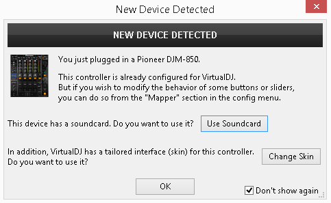
The unit is now ready to operate with VirtualDJ.
MIDI Operation
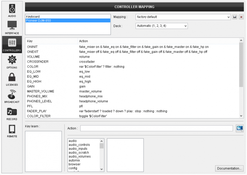
The factory default Mapping offers the functions described in this Manual, however those can be adjusted to your needs via VDJ Script actions.
Find more details at
http://www.virtualdj.com/wiki/VDJ8script.html
AUDIO Setup
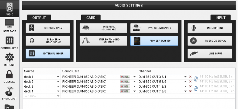
The unit has a pre-defined Audio setup and a special button in the AUDIO tab of Config to provide that. Alternative setups can be applied in the same window.
Timecode (DVS)* configuration is not pre-configured (see DVS Support for more details).
*requires Pro Infinity or Timecode License http://www.virtualdj.com/buy/index.html
For further software settings please refer to the User Guide of VirtualDJ 8.
http://www.virtualdj.com/manuals/virtualdj8/index.html
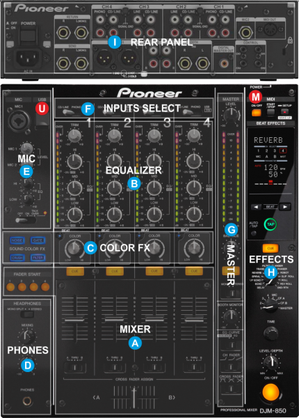
LAYOUT
U. USB Use a USB cable to connect the DJM-850 with a USB port of your computer and allow DJM-850 to send and receive audio and Midi signals
M. MIDI. Press this button to enable the MIDI Operation of the DJM-850. Once VirtualDJ is connected, press the MIDI START/STOP button for 2 seconds and a MIDI snapshot will be sent from the DJM-850 (the position of the faders and knobs of the DJM-850 will be reported to VirtualDJ)
Even though the Pioneer DJM-850 is capable of sending MIDI signals from all faders, buttons and knobs, the entire unit is not controlling the internal mixer of VirtualDJ. The audio mixing and the Effects are operated from the hardware.
The Crossfader, Equalizer, Filter, Volume faders etc. will move the relative faders of the VirtualDJ GUI, but not vice versa (Fake mixer mode)
The functionality of each button, knob and connection per section (as shown in the image above) will be explained in detail in the next chapters
A. Mixer Controls
B. Equalizer
C. Color FX
D. Headhones Controls
E. Microphone Controls
F. Inputs/Source Selects
G. Master section
H. Hardware Effects
I. Rear Panel
Mixer
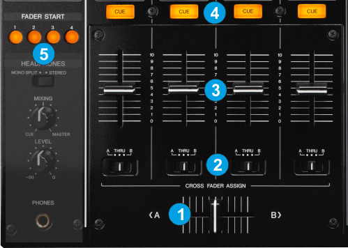
- CROSSFADER. Blends audio between the left and right assigned channels/decks.
- CF-ASSIGN. Define on which side (A for left and B for right) of the crossfader each mixer channel will be output. If the THRU position is selected, the corresponding channel will be heard regardless the cross- fader’s position.
- VOLUME. Use these faders to adjust the Output Volume of each mixer channel.
- CUE. Use these buttons to send one or more channel's pre-fader signal to the Headphones Channel for monitoring. When engaged, the button will be lit.
- FADER START. When Fader Start is enabled on a specific channel* the deck will start playing once its Volume fader moves away from the minimum position and will stop to the last Cue position when the Volume Fader reaches minimum position again.
If a channel is assigned to a Crossfader side (A or B) the deck will play once the crossfader moves away from the assigned side and will stop to the previous Cue position once reaches the other side.
*The Fader Start buttons follow the selected deck/channel order. See Mixer Channel Order.
Equalizer
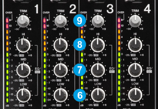
- LOW. Use these knobs to adjust the low (bass) frequencies of each mixer channel.
- MID. Use these knobs to adjust the middle (mid) frequencies of each mixer channel.
- HI. Use these knobs to adjust the high (treble) frequencies of each mixer channel.
- TRIM. Adjusts the input audio level (gain) up to +9db of each mixer channel. No boost or cut is at 12 o’clock position.
Color FX
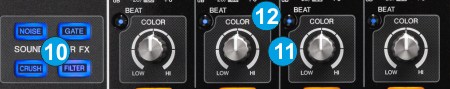
- COLOR BUTTONS. Use these knobs to select one of the 4 available Sound Color Effects (Noise, Gate, Crush and Filter).
Only one Color FX can be selected each time. The Color Effects are Hardware Effects and do not control any internal VirtualDJ Effect. - COLOR KNOBS. Use these knobs to adjust the amount of the selected Sound Color Effect to each of the Mixer channels. No Effect is applied when the knob is at 12 o’clock position.
When the FILTER is selected, even though the COLOR knobs will move the FILTER knobs of the VirtualDJ GUI, the internal High-Low Pass Filter of VirtualDJ is still not used (only provide a visual indicator) - COLOR BEAT. Then enabled, the Sound Color Effects will follow the Beat pattern from the FX section.
Headphones
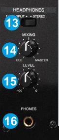
- SPLIT. When set to STEREO, both sides of Headphones will output the same CUE or MASTER Outputs (depending on the MIXING knob. When set to MONO SPLIT, one side of Headphones will output the Master and the other the CUE decks.
- PHONES MIXING Use this knob to mix between CUE and Master MIX in the Headphone channel. When all the way to the left, only channels routed to Headphones (via the CUE buttons) will be heard. When all the way to the right, only the Program mix will be heard.
- PHONES LEVEL. Use this knob to set the volume to the Headphones Channel
- PHONES INPUT Connect a pair of ¼” Headphones t this socket for monitoring
Microphone
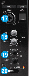
- MIC1 INPUT Connect a microphone using a XLR 3-pin plug, a balanced ¼” TRS plug or unbalanced TS plug. An additional Microphone Input is available at the rear panel as well.
- MIC LEVEL. Use these 2 knobs to adjust the Input level of Microphone Inputs 1 and 2.
- MIC EQ. Use these knobs to adjust the high/mid and low frequencies of both the Microphone Inputs.
- MIC ON/OFF/TALKOVER/ Use this switcher to run on/off the Microphone Inputs. When set to TALK OVER sound will be automatically dropping when Microphone is used.
Input Selects
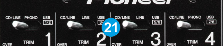
- INPUT SELECT. Set this selector to the appropriate position to define which Channel Input will be routed to the 4 Mixer Channel Outputs
Set to USB position to route a VirtualDJ deck output to a mixer channel.
On PHONO/CD/LINE position the audio signal from the Inputs (1, 2, 3 and 4 at the rear panel) will be routed directly to the Output of this Mixer Channel. In this case the sound from the computer’s decks will be muted. Use this position to route external analogue media sources.
By default VirtualDJ decks 1, 2, 3 and 4 will be routed to mixer channels 2, 3, 1 and 4 (middle channels will control the main left and right decks). Order can be changed to your needs. See Mixer Order.
Master

- MASTER LEVEL. Use this knob to control the Output level of the Master Output.
- BALANCE. Use this knob to balance between the left and right signals of the Stereo signal
- CUE MASTER. Press this button to send the signal of the Master Output to the Headphones Channel.
- MONO/STERO. When set to MONO, both left and right signals will be output to both left and right Outputs.
- BOOTH VOLUME. Use this knob to control the Output level of the Booth Output.
- EQ CURVE. Choose between Normal and Isolator (Cut) Equalizer modes.
- CH FADER CURVE. Select the Curve that the Channel Volume faders will follow.
- CROSSFADER CURVE. Select which curve the Crossfader will follow (Cut, Full, Smooth)
Effects
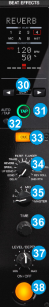 The Beat Effects section of the Pioneer DJM-850 is offering a variety of high-quality hardware beat-based effects that can be applied to any of the 4 available decks, Master, Crossfader assigned sides and both Microphone Inputs.
The Effects that come with VirtualDJ can be applied to any of the 4 decks as well, using the corresponding Effect buttons from the GUI or an additional MIDI device and will be applied before the hardware effects.
The functionality of this section is briefly described below. Please refer to the Manual of the unit for a detailed description.
- BEAT MULTIPLIER. Set the Beat fraction for synchronizing the Effect sound.
- BEAT TAP. When the BPM measurement is set to TAP, the BPM is manually input by tapping the button.
- BEAT AUTO. Switches the BPM measurement mode (auto or manual)
- EFFECT CUE. Use this button to send the applied Beat Effect output to the Headphones channel (for monitoring prior applying)
- EFFECT SELECT. Select one of the available Beat Effects.
- EFFECT CHANNEL. Select the Channel on which the Beat Effect will be applied to.
- TIME. Adjust the Time parameter of the selected Beat Effect
- EFFECT LEVEL. Adjust the quantitative parameter of the selected Beat Effect.
- EFFECT ON/OFF. Turn the selected Beat Effect on/off.
Rear Panel
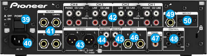
- POWER.ON/OFF. Power on the unit after all the necessary connections are done.
- POWER SOCKET. Connect a universal AC cord.
- SEND/RETURN Use balanced pairs of ¼” TS jacks for the SEND and RETURN Inputs. These Outputs/Inputs are normally used to connect outboard effect units
- INPUTS. 2 Phono/CDLINE and 2 LINE/CDLINE inputs are provided by RCA jacks (one for each Deck/mixer channel). PHONO Inputs on CH1 and CH4 can be used to connect turntables. CDLINE Inputs (in all 4 mixer channels) can be used to connect CD Players. LINE Inputs in CH2 and CH3 can be used to connect other analogue Auxiliary Sources.
- MASTER 1 (BALANCED) Connect your amplifier using a pair of balanced XLR jacks. The level of this output is controlled by the MASTER LEVEL knob at the top panel
- MASTER 2 (UNBALANCED). Connect your amplifier using a pair of RCA cables. The level of this output is controlled by the MASTER LEVEL knob at the top panel
- REC OUT. Additional unbalanced Output. Use standard RCA cables and send the Master Output to an external recording device.
- BOOTH OUT Use a pair of balanced ¼“ TRS jacks to connect the unit with your secondary output (e.g. for monitor). The level of this output is controlled by the BOOTH knob at the top panel
- DIGITAL. S/PDIF Output. Used to digitally link mixers without converting to analog.
- CONTROL. 3.5mm mini phone jack type connections. If you connect a Pioneer CDJ Player with the supplied Control cables, you will be able to start/stop playback with the Volume faders of the DJM-850.
- MIC2 INPUT Connect a microphone using a balanced ¼” TRS plug or unbalanced TS plug.
- MIDI OUT Connect this input with the MIDI IN Terminal of an external MIDI sequencer.
Note: The Master, Booth and Rec outputs arrive from the same “Main Mix” signal. The first 2 have their own LEVEL control at the top panel. Because all signals are identical, users may use any of these outputs as the “Main” output if a different cable type is required for system connection.
Advanced Setup
The Pioneer DJM-850 offers a built-in audio interface with 4 stereo Outputs and 4 stereo Inputs. The Inputs are determined by the Input Select switchers at the top panel of the unit.
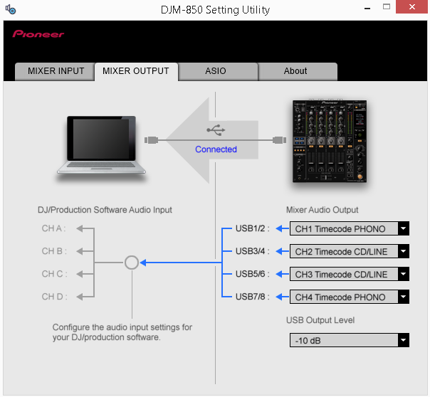
The USB Output Channels can be set to different modes via the Pioneer DJM-850 Setting Utility (automatically opens when the DJM-850 is connected to a USB port of your computer)
How to manually open:
For Windows computer:
Click [START] menu [All Programs] [Pioneer] [DJM-850] [Pioneer DJM-850 Settings Utility]
For Mac OSX computer:
Click [MACINTOSH HD] icon [Applications] [Pioneer] [DJM-850] [Pioneer DJM-850 Settings Utility]
Timecode (DVS)
VirtualDJ is offering DVS (Digital Vinyl System) support for the Pioneer DJM-850. A Timecode Plus or Pro Infinity license is required. http://www.virtualdj.com/buy/index.html
Up to 4 Timecode Inputs are available to control any software decks via Timecode CDs or Vinyls.
Mixer Channels CH1 and CH4 can accept PHONO (Timecode Vinyls). CD/LINE (Timecode CDs) can be accepted in all 4 available Channels.
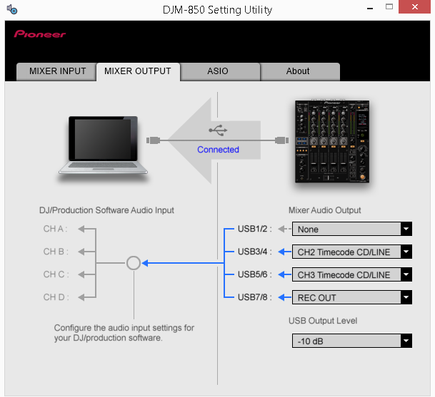
Open the Pioneer DJM-850 Setting Utility and set the USB Channel Outputs to the appropriate mode.
In this example (as shown in the side picture), 2 Timecode Vinyls (turntables) have been connected to CH1 and CH2 and 2 Timecode CDs have been connected to Ch2 and CH3
Close the Settings Utility
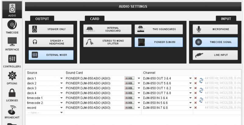
Open the AUDIO tab of VirtualDJ Settings and click on the TIMECODE button. By default VirtualDJ will auto-create 2 Timecode Inputs. Add 2 more Timecode Input lines and select the appropriate Input Channels as per the image below
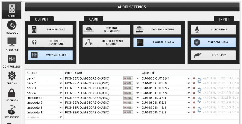
Click to APPLY.
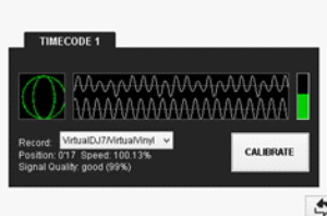
Press PLAY on your timecode CD and/or Vinyl device and VirtualDJ will automatically detect your Timecode type and make the appropriate adjustments for best performance.
Open the TIMECODE tab of the VirtualDJ Settings and choose the CALIBRATE button if for any reason the signal is not detected (possibly due to reversed phase connections).
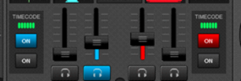
Click on the ON buttons from the TIMECODE panels of the Default Skin (in the SCRATCH center panel) to enable the Timecode control to any of the 4 software decks.
If any of the available USB Output is not used, choose None from the list.
REC OUT has been chosen for CH4 in this example. See Recording.
Recording
- Open the DJM-850 Setting Utility and set any of the 4 USB Outputs as REC OUT.
In this example, USB7/8 (CH4) has been selected as Recording Output.

- Open the AUDIO tab of VirtualDJ Settings and manually add a “record” line to your current audio configuration. Select the PIONEER DJM-850 sound card and the same Input Channels from the Setting Utility (in this case IN 7&8), as per the following image.
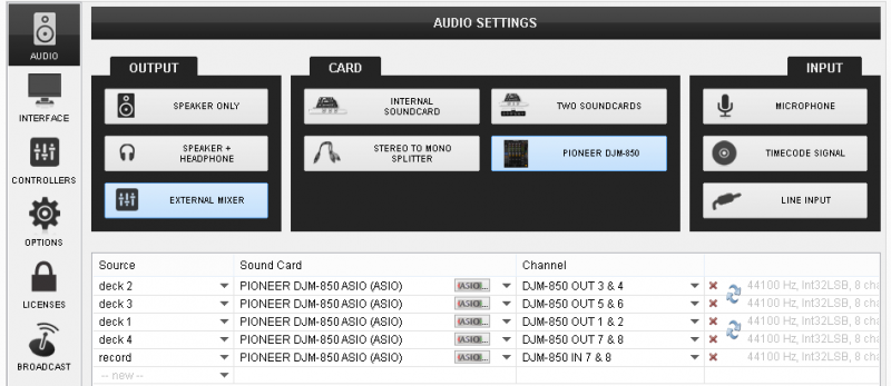
Pioneer DJM-850 - Audio Setup with Record line - Click to APPLY
- Open the MASTER center panel of the VirtualDJ GUI and click to the REC button (or BCAST for broadcasting) to record your mix.
Mixer Order
By default Pioneer DJM-850 is pre-configured to control VirtualDJ decks with order 3-1-2-4. This means that the middle CH2 and Ch3 are assigned to control main decks 1 and 2 and the side Channels CH1 and CH4 are assigned to control VirtualDJ decks 3 and 4.
How to change the Mixer channel order?
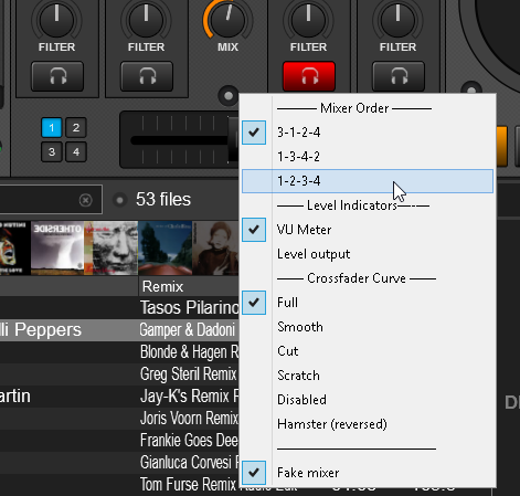
- Click on the small round button right above the Crossfader (Mixer Options) to get the Mixer Options menu. (available in the 4 Decks default GUI of VirtualDJ)
- Choose one of the available mixer orders 1-2-3-4, 3-1-2-4 (default) or 1-3-4-2
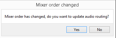
- If the sound card of the Pioneer DJM-850 is used in the Audio setup, confirm the change of the audio routing in the following window and VirtualDJ will automatically make the necessary changes to the audio configuration.